ELECTRICAL SCHEMATIC SYMBOLS MEANING DIAGRAM
Electrical symbols for solar container equipment
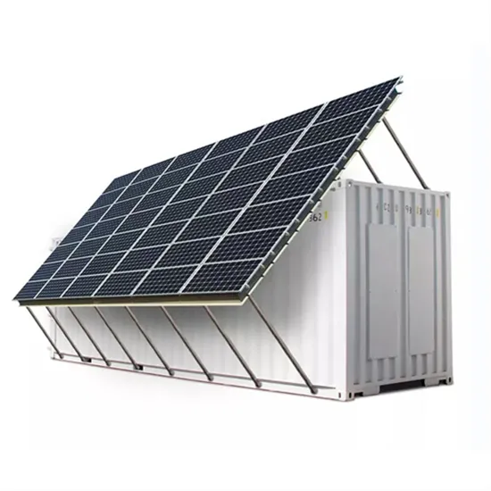
2 or 3) of the previously published IEC 60617 have been incorporated into this database that currently includes some 1900 symbols. A solar panel usually consists of many solar cells wired in series and 2-3 of those in parallel. A solar-powered container can run lighting, sound systems, medical equipment or communications gear without waiting for grid hookups. Off-grid Deciphering the mysteries of ISO container markings can seem like trying to understand a foreign language at first. Solar wiring diagram symbols come in a variety of shapes and sizes, each designed to represent a specific type of component found in a solar. Common Electrical Symbols 3 General Drafting Practices • Electrical systems should be drawn separate from other drawings such as architectural, structural, mechanical.
Read More
Inductor solar container characteristics analysis diagram
Delve into the characteristics of ideal capacitors and inductors, including their equivalent capacitance and Master capacitor energy storage and power generation calculations with our comprehensive guide. as ripple-free terminal currents and compact syste design along wi h a high step-up ratio. ́Cuk converter is a variant of the standard bu to it s, the ́Cuk converter can be designed to operate with r u-pled nductor ́Cuk converter. Inductors,as key components in electronic circuits,can be classified into various types based on structure,manufacturing process,and application. Pop Up Power Supplies® works closely with a wide range of construction professionals at any given point in the Specification process. The LCL filter model is where L1 is the inverter side inductor, L2 is the grid-side inductor, Cf is a capacitor with a series Rf damping resistor, R1 and R2 are inductors resistances, and voltages vi and Learn about the fundamental concepts of inductors and capacitors in electronics.
Read More
Battery solar container working principle diagram explanation
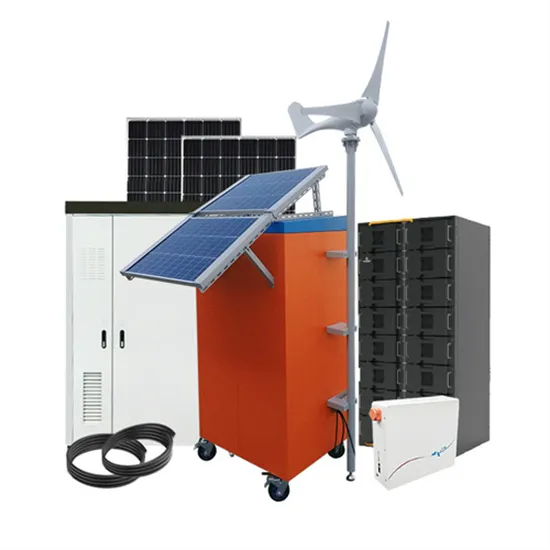
A solar energy storage system diagram is the foundational roadmap for any successful solar power installation. It's more than just a drawing; it is a detailed plan that illustrates how every component connects and interacts to generate, store, and deliver power. We'll walk you through how energy storage systems work with solar, what you can expect from your setup, and what's actually happening inside that battery when it stores your excess solar energy. What is a schematic diagram of a solar power system? The schematic diagram of a solar power system provides a visual representation of how different components work together to harness solar energy and convert it into usable electricity. Photovoltaic panels: Learn about the crucial role of solar panels in converting sunlight into electricity.
Read More
Base station solar container principle diagram analysis
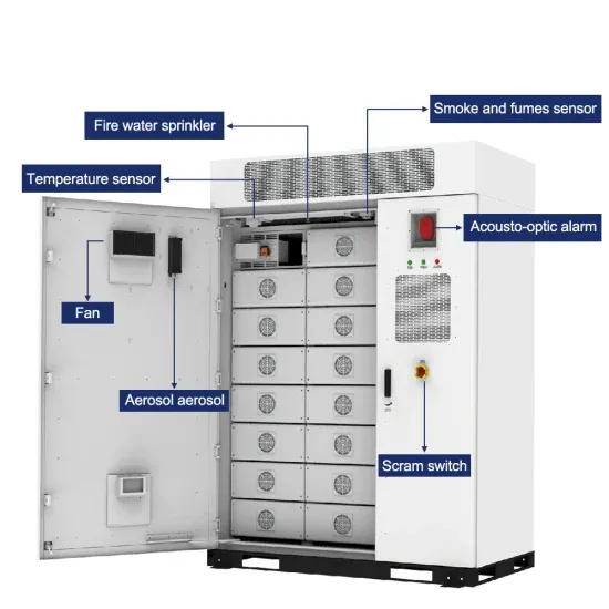
In this deep dive, we'll unpack why these technical drawings are the secret sauce for successful BESS (Battery Energy Storage System) projects, complete with real-world examples that'll make you rethink "boring" engineering document. Working principle of high-speed container power ustomizable solutions for generating and storing solar power. What is the sleep mechanism of a base station? The sleep mechanism of a base station refers to the intelligent shutdown of major power consumption devices, such as the AAU of the base station, when there is no load or the load is low, such that the energy consumption is greatly reduced. Ever wondered what keeps those massive battery containers from doing the electric slide during extreme weather? Enter the energy storage power station container foundation diagram - the unsung hero of renewable energy infrastructure.
Read More
Diagram of the working principle of the switch solar container motor
Automatically switches between the solar panel/battery system and the AC supply, ensuring continuous power supply to the load. A photovoltaic panel that converts sunlight into electrical energy, which is then used to charge the battery or power the load directly. ITEMS used in this tutorial include Solar Panels, 2 MCB, Charge Controller, Battery, Inverter, LDR, ATS Ac Bulb, Neutral bars, earth bar, energy meter. What is a schematic diagram of a solar power system? The schematic diagram of a solar power system provides a visual representation of how different components work together to harness solar energy and convert it into usable electricity. Aach the wire connected to the motor to the centre peg using the heat shrink (place the heat. the generation of a potential difference at the junction of two different materials in response to electromag-netic radiation.
Read More
Reasons why switching electrical equipment cannot store energy
Predominantly employed in electrical circuits, switches act as physical barriers that either allow or disrupt the flow of electricity. The inability of a switch to store energy lies in its function as a control device, not a storage medium, 2. Conduction losses can be observed in BJTs, IGBTs, and MOSFETs (metal-oxide-semiconductor field-effect transistors). This article isn’t just for sparky engineers – it’s for curious DIYers, smart home enthusiasts, and anyone who’s ever zapped themselves changing a light bulb (we’ve all been there). These technologies work together to monitor, manage, and distribute electricity dynamically, maintaining grid stability even as demand fluctuates and renewable energy sources add variability to the system.
Read More