WORKING PRINCIPLE OF BLDC MOTOR BRUSHLESS DC MOTOR DIAGRAM
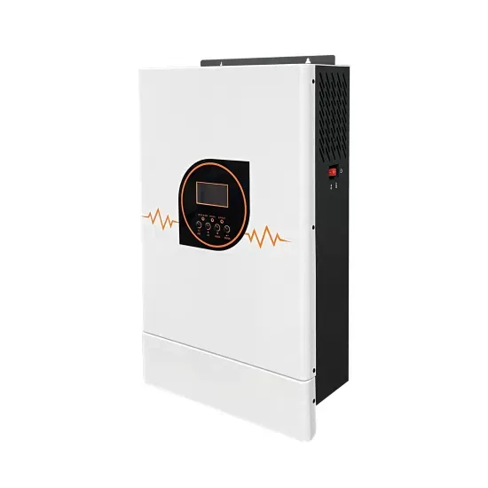
Diagram of the working principle of the switch solar container motor
Automatically switches between the solar panel/battery system and the AC supply, ensuring continuous power supply to the load. A photovoltaic panel that converts sunlight into electrical energy, which is then used to charge the battery or power the load directly. ITEMS used in this tutorial include Solar Panels, 2 MCB, Charge Controller, Battery, Inverter, LDR, ATS Ac Bulb, Neutral bars, earth bar, energy meter. What is a schematic diagram of a solar power system? The schematic diagram of a solar power system provides a visual representation of how different components work together to harness solar energy and convert it into usable electricity. Aach the wire connected to the motor to the centre peg using the heat shrink (place the heat. the generation of a potential difference at the junction of two different materials in response to electromag-netic radiation.
Read More
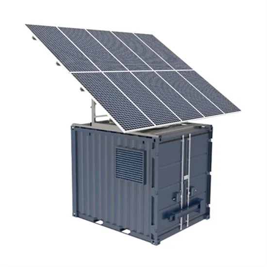
Home solar container working principle diagram explanation
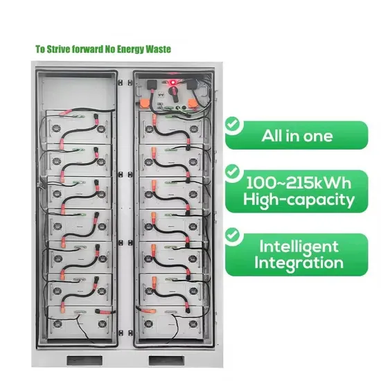
Explore a step-by-step breakdown of how solar containers harness and store solar energy. Understand the process of converting sunlight into DC electricity through photovoltaic panels. In this ultimate guide, we will break down a diagram of a solar power system and explain each element’s function and importance. What are self-contained solar energy containers? From portable units to large-scale structures, these self-contained systems offer customizable solutions for generating and storing solar power. The solar inverter circuit diagram typically includes the following components: Solar Panels: These are.
Read More
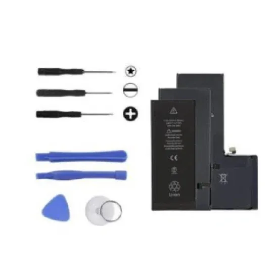
Battery solar container working principle diagram explanation
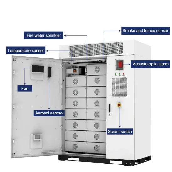
A solar energy storage system diagram is the foundational roadmap for any successful solar power installation. It's more than just a drawing; it is a detailed plan that illustrates how every component connects and interacts to generate, store, and deliver power. We'll walk you through how energy storage systems work with solar, what you can expect from your setup, and what's actually happening inside that battery when it stores your excess solar energy. What is a schematic diagram of a solar power system? The schematic diagram of a solar power system provides a visual representation of how different components work together to harness solar energy and convert it into usable electricity. Photovoltaic panels: Learn about the crucial role of solar panels in converting sunlight into electricity.
Read More
Solar container motor implementation standards
The new EU Battery Regulation represents a significant shift in the way batteries are manufactured, imported, distributed, and managed, particularly for the solar energy storage sector. 's wake-up calls, European enterprises prioritize ironclad BESS Container Safety Standards. Do solar products need to comply with revised Indian Standards? The products need to comply with the revised Indian standardsas notified in the new QCO: Solar Systems,Devices and Components Goods Order,2025 which is as follows: 1. When you're about to roll out containerized solar systems--for a Haitian humanitarian mission or a telecom project in Namibia--you'll soon have to answer a crucial question: what certifications should solar containers have to ensure safety, performance, and compliance with regulations? Solar. The safe and reliable installation of photovoltaic (PV) solar energy systems and their integration with the nation’s electric grid requires timely development of the foundational codes and standards governing solar deployment.
Read More
Working principle of iron-chromium liquid flow solar container battery
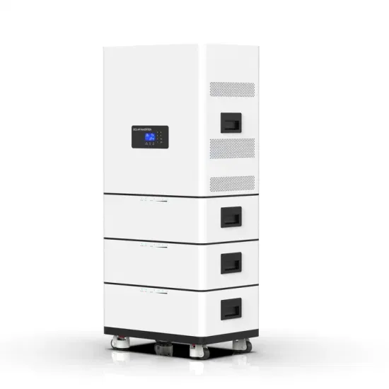
Energy is stored by employing the Fe2+ – Fe3+ and Cr2+ – Cr3+ redox couples. The active chemical species are fully dissolved in the aqueous electrolyte at all times. This paper aims to introduce the working principle, application fields, and future development prospects of liquid flow batteries. Fluid flow battery is an energy storage technology with high scalability and potential for integration with renewable energy. 000titleclaimsabstractdescription7 The invention relates to the technical field of power supply systems, in particular to an iron-chromium liquid flow energy storage battery system which comprises a wind power generation device, a reaction container, a first liquid.
Read More
Magnetic motor solar container capacitor
Unlike capacitor banks, they’re modular (scalable from 100kWh to 10MWh), fast-acting (response times under 20ms), and multi-functional (they store energy and manage reactive power). For EU grid operators and industrial facilities, this isn’t just an upgrade—it’s a necessity. Maintaining power quality is critical for renewables and large-scale industrial operations— to protect equipment lifespan, minimize downtime and maximize eficiency. It consists of two conductive plates separated by an insulating material known as a dielectric. When a voltage is applied across the plates, electric charge accumulates, allowing the capacitor to temporarily. Enter BESS Container in EU Grid Reactive Power Compensation: these compact, inverter-equipped power pros respond in 20ms to supply or absorb reactive power, slashing voltage drops (75% in German factories!) and cutting 10-year costs by 35% vs.
Read More